


Micro Project 1.2:
Site Allocation and Measuring
Micro Project 1.2 was the second part to the first design project.
Being a larger project then the first part we were allowed to pick a site on one of the chosen streets from the project previously.
Being fond of Pink Lane I was lucky to find a site with interesting details including a beautiful windowed arch spanding the majority of the ground floor.
Measuring the site was a major part in this project as it would become vital in order to produce the drawings and model later on in the project.
Using a laser measure at a particular point on the ground, I measured the distance from the ground point to the building and then a second measure to the top of the building. With these two measurements I applied pythagoras to determine the height of my building.
For smaller details in harder to react places such as the top windows I had to rely on counting and measuring the bricks and mortar.


Micro Project 1.2:
Photographic Joiner
Starting with a photographic joiner, I unfortunately at the time had a broken camera rendering me unable to use my SLR meaning I had rely on two disposable cameras.
Using a disposable camera had its advantages, It allowed me to have different images to have a range of contrasts and gave my overall joiner an interesting style.
However, it did come with its disadvantages also, each photo was a gamble. The not knowing how the photos are going to come out was a nerve-raking experience. With a disposable you have a lack of settings opting for a simple point and click. This resulted in me being unable to experiment with shutter speed or brightness.


Micro Project 1.2:
1:50 Model and Elevation
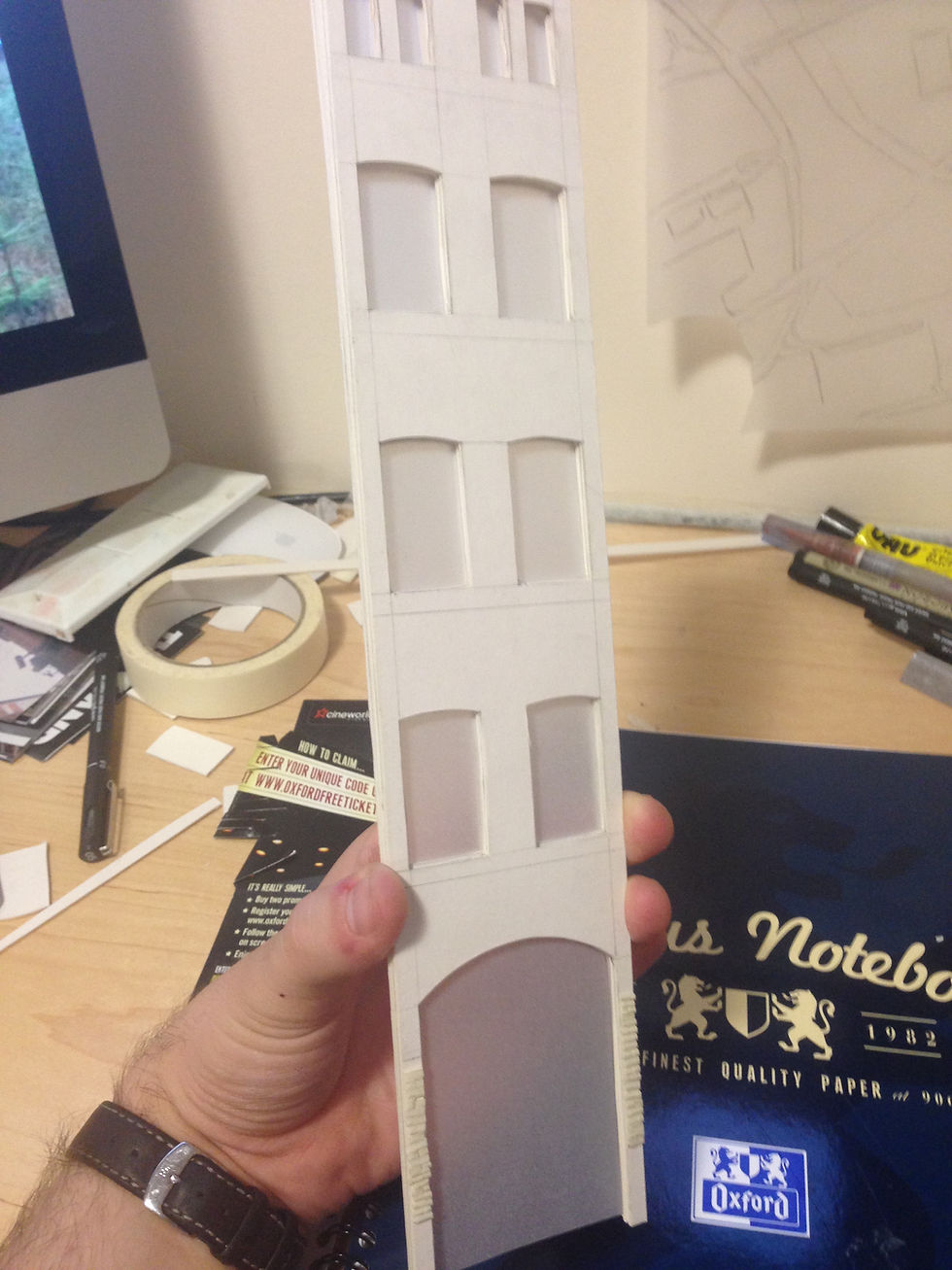
Having taken the measurements for my site and studied through a photographic joiner I was confident in undergoing the next task of creating a 1:50 scale model of my buildings facade.
Using white card and tracing paper, for the windows and central archway I created the model to have a simplistic style opting to focus more on the detailing rather that the materiality of the building.
Making the model out of white card came with the disadvantage of collecting alot of pencil marks and resulted in my model becoming rather scruffy losing its prestine crisp whiteness.


Micro Project 1.2:
1:20 Rendered Section
The final component to project 1.2 was the 1:20 rendered elevation that consisting of only the ground floor to 1st floor windows. This drawing was to show a greater detail as apposed to the 1:50 elevation.
Using a pencil render allowed me to apply a more controlled shading and the safer aspect of if a mistake occured it could easily be erased. Using mainly softer pencils for the shading and shaping of the brick to the harder pencils to apply a stronger outline for places such as under the window sill and ground line.
Having the arched window take up the majority of the ground floor entitled me to render the windows reflection rather than just have a soild mass in the centre which would have drawn the eye away from the rest of the drawing resulting in a ruined piece.
Knowing this, I decided to render the reflection also. Once finished I applied eraser streaks on each panel of glass to give the illusion of reflected glass rather than distorting the reflected view.
The 1:50 model became useful in the sense that it could now be used as a visual reference in completing the task of producing an elevation drawing of the same scale.
Along with the measurements and the model, the drawing, a simple pencil line devised using different line strengths. Leaving the construction lines on the drawing allow for an interesting visual reference.


